The firing outputs of the PFE Advanced 10 and 20 Outputs can directly drive magnetic valves (also called solenoids).
The coil of every magnetic valve is an inductive load.
Every inductive load creates a high voltage peak when it is switched off. This is called self-inductance. This voltage peak has the opposite polarity of the supply voltage.
In order to prevent that this high voltage peak is causing any damages it is general practice that a freewheeling diode is used whenever an inductive load is switched. This diode will short circuit the unwanted voltage peak.
There is already an internal freewheeling diode in the PFE Advanced 10/20 Outputs but if the energy is too much a separate freewheeling diode is necessary. In Addition, it is standard practice to use a freewheeling diode and to put it as close to the load as possible.
For coils with up to 35 Watts the standard type 1N4007 can be used. That is a silicon diode that can withstand 1,000 Volts and has a current rating of 1 Ampere. For coils with 35 to 100 Watts the diode 1N5408 can be used.
In general, the freewheeling diode should be used always as close to the coil as possible to eliminate ringing or other adverse effects.
The anode of the diode must be connected to the negative output terminal of the firing module and the cathode of the diode to the positive output terminal.
Please mind polarity when you connect the coil to the firing module. Otherwise the diode will cause a short circuit and it will be destroyed instantly when the output is switched on.
Many electrical connectors for magnetic valves already contain a freewheeling diode. In this case you must also mind polarity. Usually polarity is marked on these connectors.
If you do not use freewheeling diodes the firing module can be damaged and malfunctions of any kind can occur.
It may also be advisable to check the functionality of the freewheeling diodes, because if the freewheeling diode has been destroyed due to incorrect polarity, this may initially not be noticed. To do this, disconnect one terminal of the diode or disconnect the coil and then test the diode with a multimeter (diode test function). In flow direction approx. 0.7 Volts should drop at a normal silicon diode. If Schottky diodes are used, then approx. 0.15 to 0.3 Volts are to be expected.
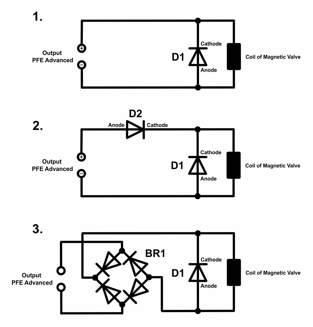
Please see the adjacent circuit diagrams.
The first one shows the simplest solution that is described above. The diode will be destroyed if polarity is not minded.
The second one has an additional diode D2 that protects the freewheeling diode from being damaged if polarity is not minded. In case of wrong polarity, no current can flow and the valve remains closed (assuming a valve that is normally closed). This diode must be able to withstand the continuous current of the coil. As D2 a 1N4007 can only be used for small coils up to 1 Ampere. 1N5408 is suitable for coils up to 3 Ampere. For even heavier coils up to 10 Ampere e.g. MBR10100 can be used. Cooling with a heat sink might be necessary here.
The third diagram shows the most sophisticated and best solution. Here a bridge rectifier BR1 is used so that polarity does not need to be minded at all. In this case you do not need to pay attention regarding the polarity when you connect the circuit to the firing module. The bridge rectifier can be built up by individual diodes or you can use a bridge rectifier module. Again, the diodes in the rectifier must be able to withstand the continuous current of the coil. For up to 2 Ampere the BXXXR series from Diotec Semiconductor is suitable. XXX stands for the maximum Voltage the rectifier can handle. The KBPC25XX/W or the GBI25X series from the same manufacturer can handle up to 25 Ampere if cooled with a heat sink.
Please do not hesitate to contact us if you have any questions. It is also recommended to forward this information, which is quite difficult to understand by non-specialists, to professionals who can then offer a solution on the job.

